Timber frame construction
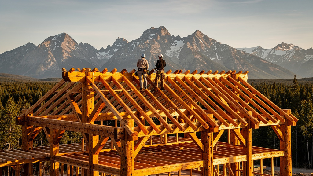
Timber framing is one of humanity's oldest permanent construction methods. It uses large-section wood members — posts, beams, and braces — connected with interlocking wood joinery rather than metal fasteners or nails. The result is a structure that is extremely strong, dimensionally stable, and visually striking. A timber frame building properly maintained will last 300–500 years. Traditional barns still standing from the 1700s in New England are evidence of this.
For a preparedness-focused owner-builder, timber framing is attractive because it uses locally sourced, natural materials; produces structures that are highly resilient to wind and seismic loads; and can be built with hand tools when power is unavailable. A basic 16 × 24 ft (4.9 × 7.3 m) timber frame cabin shell — posts, beams, rafters, and rough sheathing — represents a significant investment in materials, with the bottom of the range reachable when an owner-builder mills timbers from a local woodlot and the top reflecting purchased graded timbers, hired sawmill work, and a finished metal roof. See the Cost Summary below for component breakdown.
This page walks through the full build sequence. It assumes you are comfortable with basic carpentry but have never cut traditional timber joinery before. See Carpentry for foundational skills.
Educational use only
This page is for educational purposes only. Hands-on skills should be learned and practiced under qualified supervision before relying on them in emergencies. Use this information at your own risk.
Action block
Do this first: Contact your local Authority Having Jurisdiction (AHJ) — typically your county building department — and download their residential structural permit application; note whether engineered drawings are required for your structure size (30 min) Time required: Active: 30 min permitting research + 3–5 days joinery practice cuts before committing to structural members; construction: 2–4 weeks for a 16×24 ft (4.9×7.3 m) shell with a crew; raising day: 1–2 days Cost range: Significant investment for materials (timbers, foundation, sheathing, roofing); moderate investment for hand tools if not already owned; affordable for permit fees; engineering review is a moderate investment for spans beyond standard sizing guidelines Skill level: Intermediate for foundation and layout work; advanced for mortise-and-tenon joinery; expert for raising coordination and structural sizing beyond the table minimums in this guide Tools: Timber framing square; mortise gauge; timber chisels (1 in / 25 mm, 1.5 in / 38 mm, 2 in / 50 mm); slick (long-handled paring chisel); brace and bit or electric drill with 1.25 in (32 mm) auger bit; circular saw or chainsaw; 12 ft (3.7 m) pike poles (6–10 for raising day); post level; sledgehammer. Supplies: anchor bolts (1/2 in / 13 mm J-hooks); sill seal foam gasket; stainless steel shims; hardwood pegs (1.25 in / 32 mm diameter); hurricane ties (Simpson H2.5 or equivalent); end grain sealer; penetrating oil finish. Safety warnings: See Keep crew clear of falling timber below — a falling bent can travel 25 ft (7.6 m) from its base and is immediately lethal to anyone in its arc
Understanding Timber Frame Structural Logic
Before cutting wood, you need to understand how the loads flow through the frame.
Gravity load path: Roof → rafters → purlins → tie beams → posts → sill → foundation. Every member must be sized to carry the loads transferred to it from above.
Lateral load resistance: Wind and seismic forces are resisted by diagonal knee braces connecting posts to beams, by shear walls (structural sheathing panels), and by the rigidity of the joinery itself. A frame without adequate diagonal bracing will rack (lean sideways) under lateral load.
Bay spacing: A bay is the space between two adjacent bents (wall frames). Standard bay spacing for residential timber frames is 16–20 ft (4.9–6.1 m) in the long direction and 16–24 ft (4.9–7.3 m) in the width direction. Wider bays require larger beams — doubling bay width requires roughly four times the beam section for the same load.
Post spacing in width (bent spacing): Bents are typically spaced at 16 ft (4.9 m) centers for a modest house or barn. A two-bay structure has three bents. A three-bay structure has four bents.
Step 1 — Species Selection and Sizing
Choose your timber species based on what is available locally, your structural requirements, and your budget.
| Species | Bending Strength (Fb), Select Structural | Hardness | Relative cost | Best Use |
|---|---|---|---|---|
| Douglas Fir-Larch (Pacific NW) | ~1,500 psi (10.3 MPa); No.1 ~1,200 psi; No.2 ~875 psi | Hard | Moderate | Posts, beams, all-purpose framing |
| Eastern White Pine | ~900 psi (6.2 MPa); No.2 ~575 psi | Soft | Affordable | Rafters, purlins, secondary members |
| White Oak | ~1,100 psi (7.6 MPa) | Very hard | Significant | Joinery-heavy frames, traditional New England |
| Southern Yellow Pine | ~1,400 psi (9.7 MPa) | Hard | Affordable | Southeast US; excellent for beams |
| Hemlock-Fir | ~1,000 psi (6.9 MPa) | Medium | Affordable | Northeast US; common and widely available |
| Black Locust | Strong; specific NDS values not tabulated for all sizes | Very hard | Moderate | Sill plates (extremely rot resistant) |
Values are NDS Table 4A/4D reference design values for Select Structural grade — actual Fb depends on grade (Select, No.1, No.2, No.3) and size class (Beams & Stringers vs. Posts & Timbers). Grade down significantly for ungraded or owner-milled timber.
Minimum sizing guidelines for a single-story residential structure with a 30 lb/sq ft (1.44 kPa) live load roof per AWC NDS Table 4A design values and IRC Section R802 roof framing span tables:
| Member | Minimum Section | Notes |
|---|---|---|
| Corner posts | 6 × 6 in (140 × 140 mm) | 8 × 8 in for two-story |
| Intermediate posts | 6 × 6 in (140 × 140 mm) | |
| Major beams (tie beam, summer beam) | 6 × 10 in (140 × 235 mm) for 16 ft span | Size up for wider bays |
| Rafters | 4 × 6 in (89 × 140 mm) at 24 in (61 cm) OC | For spans to 12 ft (3.7 m) |
| Sill plate | 6 × 6 in (140 × 140 mm), rot-resistant species | Elevate off concrete |
| Knee braces | 4 × 4 in (89 × 89 mm), 45° angle | 24 in (61 cm) minimum arm length |
For spans beyond these guidelines or for second-story loads, hire a licensed structural engineer to size your members. Engineering fees are a moderate investment for a simple timber frame.
Step 2 — Foundation Preparation
Timber frames are typically placed on a sill plate — a horizontal timber member anchored to the foundation perimeter. The sill must be level, square, and anchored to resist uplift and sliding.
- Pour the concrete foundation — perimeter stem wall or continuous footing, extending 12 in (30 cm) minimum above grade. Width: 8 in (20 cm) minimum for a 6 × 6 in (140 × 140 mm) sill.
- Set anchor bolts (1/2 in (13 mm) diameter, 12 in (30 cm) long J-hooks) at 4 ft (1.2 m) centers. Position anchor bolts 6 in (15 cm) from each corner and 18 in (46 cm) from planned post locations — you do not want a bolt directly under a post mortise.
- Install a sill seal (closed-cell foam gasket tape) between the concrete and the sill to prevent capillary moisture wicking.
- Lay the sill plate — use rot-resistant black locust, white oak, or pressure-treated timber for the sill. Mark post locations on the sill with a marking gauge before drilling anchor bolt holes.
- Check diagonal: Measure diagonally corner to corner in both directions. The two diagonal measurements must match within 1/4 in (6 mm) — this is your squareness check. Adjust sill position before the bolt nuts are tightened.
Field note
Get the sill perfectly level before doing anything else. A sill that is 1/4 in (6 mm) out of level becomes 1 in (25 mm) of out-of-plumb at the top of an 8 ft (2.4 m) post. Shim the sill with stainless steel plate shims before tightening anchor bolts. Galvanized or plain steel shims will rust and stain the sill.
Step 3 — Timber Layout and Joinery Marking
Traditional timber framing uses a mortise and tenon joint as its primary connection. The tenon (a projecting tongue cut on the end of a beam) fits into the mortise (a rectangular cavity cut into the post). Wooden pegs (trennels or treenails) lock the joint mechanically.
Tools required:
- Timber framing square (24 in (61 cm) framing square)
- Marking gauge (mortise gauge)
- Timber scribe (for scribing joint marks)
- Circular saw or chainsaw (rough cuts)
- Timber frame chisels: 1 in (25 mm), 1.5 in (38 mm), 2 in (50 mm)
- Slick (long-handled paring chisel, 2–3 in (50–75 mm))
- Brace and bit or electric drill with 1.25 in (32 mm) auger bit for peg holes
- Mallet (2–3 lb (0.9–1.4 kg) wood or rubber)
Standard mortise and tenon dimensions:
| Application | Tenon Width | Tenon Thickness | Tenon Length | Mortise |
|---|---|---|---|---|
| Beam-to-post | 1/3 post width | 1/3 post width | 4–5 in (100–127 mm) | Match tenon + 1/4 in (6 mm) |
| Tie beam shoulder | Full beam width - 1.5 in (38 mm) | 2 in (50 mm) | 4 in (102 mm) | Match tenon |
| Brace-to-post | 3 in (76 mm) | 1.5 in (38 mm) | 3 in (76 mm) | Match tenon |
Layout sequence:
- Mark the reference face of every timber with a lumber crayon — all layout measurements come from this face.
- Use the mortise gauge to scribe all mortise outlines — the gauge maintains consistent dimension from the reference face.
- Mark tenon shoulders with a framing square at exact right angles to the timber length.
- Mark peg hole locations: a single 1.25 in (32 mm) peg centered through the mortise, positioned 2 in (50 mm) from the tenon shoulder.
Step 4 — Cutting Joinery
Cutting a mortise:
- Drill out the waste with a 1 in (25 mm) auger bit, making overlapping holes within the mortise outline.
- Pare the sides flat with the 1.5 in (38 mm) chisel, working from both faces toward the center.
- Pare the ends square with a 1 in (25 mm) chisel.
- Check with a small square — the mortise walls must be flat and perpendicular to the timber face.
- Depth: mortise depth should equal tenon length plus 1/4 in (6 mm) bottom clearance.
Cutting a tenon:
- Saw the tenon shoulders with a circular saw or hand crosscut saw to the layout lines.
- Saw the tenon cheeks with a bandsaw, frame saw, or circular saw with a guide.
- Pare the cheek surfaces with the slick until they are flat and fit the mortise snugly. The tenon should slide in with hand pressure — not pounded, not loose.
Pegging:
- Assemble the joint dry. Drill the peg hole through the mortise side walls and through the tenon, with the peg hole offset 1/16 in (1.5 mm) toward the shoulder — this is called "draw-boring" and it pulls the joint tight as the peg is driven.
- Drive a tapered hardwood peg (1.25 in (32 mm) diameter, 10–12 in (25–30 cm) long) through the hole with a mallet.
- The peg should protrude 1/2 in (13 mm) on each side when fully seated.
Step 5 — Assembling Bents
A bent is a complete wall frame — two posts, a tie beam connecting them, and knee braces. Bents are assembled flat on the deck or ground before being raised into position.
- Lay the posts and tie beam flat on a level surface (saw horses or timber blocks) in their assembled position.
- Drive tenons into mortises for all joints. All pegs are installed now, while the work is at ground level.
- Check the bent for square: measure diagonally corner to corner. Both diagonals must match within 1/8 in (3 mm).
- Install knee braces: the braces run at 45° from post to beam, with the brace tenon driven into mortises in both the post and the beam. Knee brace length (measured along the brace itself) is typically 28–34 in (71–86 cm) for a 20 in (51 cm) arm length.
- Mark each bent clearly — a permanent lumber crayon mark on a non-visible face. Bent 1 (end), Bent 2 (first interior), etc.
Step 6 — Raising Sequence
The raising is the most dramatic — and most dangerous — step. Plan carefully and have adequate crew. Raising a single bent for a 16 × 24 ft (4.9 × 7.3 m) structure requires 6–10 people and takes a full day for an experienced crew. First-timers should plan two days.
Safety rules:
- Never stand under a rising bent
- All crew members must know the hand signals before raising begins
- Temporary bracing must be installed before any bent is released by the crew
- Work shoes with ankle support only — no sandals, no loose clothing
Raising sequence:
- Position temporary staging (2 × 4 in / 38 × 89 mm braces anchored to the sill) on the exterior of each post position. These catch the post bottoms as the bent comes up.
- Place post bases: set the post tenons (or post bases) into the sill mortises. The posts pivot around this point as the bent rises.
- Raise the first end bent: using pike poles (12 ft (3.7 m) long pushing poles) or a crane, push the bent from horizontal to vertical. One crew member per post base to keep it from sliding; remaining crew push with pike poles.
- Plumb and brace the first bent: immediately after it is vertical, install two temporary diagonal braces from the bent to the sill on each side. Check plumb with a level before releasing the pike poles.
- Raise the second bent (opposite end).
- Install tie beams connecting the two end bents at the top. These are lifted into position and their tenons driven into the post mortises by a crew member on a ladder or scaffold.
- Raise interior bents in sequence. Each new bent is connected to the previous one by tie beams before being released.
- Install purlins (horizontal members connecting bents along the roof slope) once all bents are standing and permanently braced.
Keep crew clear of falling timber
If you are raising a bent without a crane, pike poles must be long enough to keep crew members clear of the falling arc of the timber. For a 10 ft (3 m) post, use pike poles at least 12 ft (3.7 m) long. A falling bent can travel 25 ft (7.6 m) from its base.
Step 7 — Structural Sheathing and Hurricane Ties
The timber frame itself carries gravity loads. Lateral loads (wind, earthquake) are resisted by structural sheathing panels and by the frame joinery.
Structural sheathing:
- Install 7/16 in (11 mm) oriented strand board (OSB) or 1/2 in (13 mm) plywood on all exterior walls, nailed to secondary framing (2 × 4 in / 38 × 89 mm studs infilled between timber posts) at 6 in (15 cm) on center at panel edges and 12 in (30 cm) in the field.
- Alternatively, install structural insulated panels (SIPs) directly between timber posts. SIPs provide both sheathing and insulation in one operation.
Hurricane ties:
All rafter-to-plate connections and all post-to-sill connections must be reinforced with metal hurricane ties in areas with design wind speeds above 90 mph (145 km/h) — check your local building code for the design wind speed requirement per IRC Table R301.2(1) (Climatic and Geographic Design Criteria) and ASCE 7 wind speed maps for your location. Use hurricane ties rated H2.5 or equivalent per their manufacturer's listed load capacity.
Step 8 — Weatherproofing and Enclosure
With the frame up and sheathed, proceed with roofing, windows, and doors. See Weatherproofing for the full sequence.
Key timber-specific details:
- All post bases must be elevated off concrete or masonry with a post base connector that provides a 3/4 in (19 mm) air gap. Post bases sitting in standing water will rot in 5–15 years even with treated wood.
- All exposed timber end grain (particularly rafter tails and purlin ends) must be sealed with end grain sealer or two coats of boiled linseed oil. End grain absorbs water 10× faster than face grain.
- Apply a penetrating oil finish (tung oil, danish oil, or exterior-rated timber oil) to exposed interior timbers once and re-apply every 5–10 years. This prevents surface checking (cracking during drying) and keeps the wood from dulling.
Cost Summary
Total cost for a 16 × 24 ft (4.9 × 7.3 m) timber frame shell is a significant investment. The component split by relative weight:
| Component | Relative cost weight | Notes |
|---|---|---|
| Timbers | Largest single line item (roughly 40% of shell cost) | Owner-milled drops this share substantially; purchased graded timbers raise it |
| Roofing (metal, basic) | Second-largest | Metal panel cost dominates; standing-seam is significantly more than corrugated |
| Sheathing (OSB or SIPs) | Third-largest | SIPs are multiple times the cost of OSB but include insulation |
| Windows and doors (rough frames) | Moderate | Highly variable with quality tier |
| Foundation | Moderate | Pier or rubble-trench is far less than full perimeter stem wall |
| Fasteners, hardware, hurricane ties | Smallest | Stable across project sizes |
Interior finishing (insulation, drywall, flooring, utilities) adds an additional significant investment, often equal to or exceeding the shell cost depending on finish level.
Common Mistakes
| Mistake | Consequence | Prevention |
|---|---|---|
| Green (unseasoned) timber | Severe checking and twist as it dries | Use air-dried or kiln-dried timber where possible; expect minor checking in green timber |
| Mortises too tight | Joint cannot be assembled; wood splits | Target a hand-pressure fit — slide with light mallet taps |
| No draw-bore | Joint loosens as wood dries | Always draw-bore peg holes before pegging |
| No temporary bracing | Bent falls during raising | Install bracing before releasing pike poles |
| Post base in standing water | Rot in 5–15 years | Always use elevated post base connectors |
With the frame complete, proceed to Weatherproofing for roofing, drainage plane, and moisture-protection details. For insulating between and around the timber members, see Insulation. The foundational woodworking skills behind every joinery cut are covered in Carpentry, and the specific hand tools — chisels, mallets, saws, and layout equipment — are catalogued in Hand tools. For an owner-built, low-embodied-energy infill system compatible with a timber frame, Cob building covers the mix design and application sequence.
Sources and next steps
Last reviewed: 2026-05-17
Source hierarchy:
- AWC National Design Specification (NDS) for Wood Construction (Tier 1, American Wood Council standards body — reference design values for timber species, member sizing, and connection design)
- International Residential Code (IRC) — Chapter R802 Roof Framing and R301.2 Climatic and Geographic Design Criteria (Tier 1, ICC model building code adopted by most US jurisdictions — span tables, load assumptions, and wind speed design criteria)
- Timber Framers Guild — Technical Resources (Tier 2, trade organization founded 1985 — bent assembly sequencing, raising crew guidance, and traditional joinery proportions)
Legal/regional caveats: Timber frame structures meeting the definition of a "building" under state law require a building permit in virtually every US jurisdiction. The AHJ determines whether owner-drawn plans are acceptable or whether licensed engineering stamps are required — this varies significantly by county and structure size. In most jurisdictions, structures over 200 sq ft (18.6 sq m) require permits; many counties require engineered drawings for any habitable structure regardless of size. Some rural counties and unincorporated areas have minimal oversight, but this should be verified, not assumed. Check with your county building department before breaking ground.
Safety stakes: high-criticality topic — recommended to verify thresholds before acting.
Next 3 links:
- → Weatherproofing — roofing, drainage, and moisture details that protect the frame after raising; post-base and end-grain sealing covered in depth
- → Carpentry skills — foundational woodworking required before attempting mortise-and-tenon joinery — layout, measurement, chisel technique
- → Cob building — compatible natural infill material for timber frame walls; combines with the frame for a fully owner-built, low-embodied-energy enclosure